Poor Man’s Breadboard Arduino
A note from July 6, 2018⌗
When I was in high school, I wrote a short post on building a low-cost Arduino on a breadboard. It’s been quite some time since I’ve done any significant hardware hacking, but since my old blog is mostly dead at this point I reproduce that post here
I’ve burnt out a few Arduinos recently, and have found it expedient to just build my own on a breadboard rather than pay $34.95 and buy an Arduino Duemilanove online. It’s cheaper ($7.40, without FTDI or breadboard, SparkFun), and easy to fix if something goes wrong. Note that this tutorial does NOT include a voltage regulator, power will come from the FTDI board.
Parts List (minimum, of course):
- 170 tie point breadboard ($3.95)
- ATMega328P w/ Arduino Bootloader ($5.50)
- 16mhz resonator ($0.95)
- 10 kOhm resistor ($0.25)
- 100uF Capacitor ($0.35)
- SparkFun 5v FTDI Breakout ($14.95)
- Assorted wires ($0.00, you can pull them from anything)
- [optional] LED, for pin 13. ($0.35)
All prices are from SparkFun, which is NOT the cheapest. Note that the capacitor and the SparkFun FTDI can be reused across many boards, and thus the costs is divided among all the boards you build.
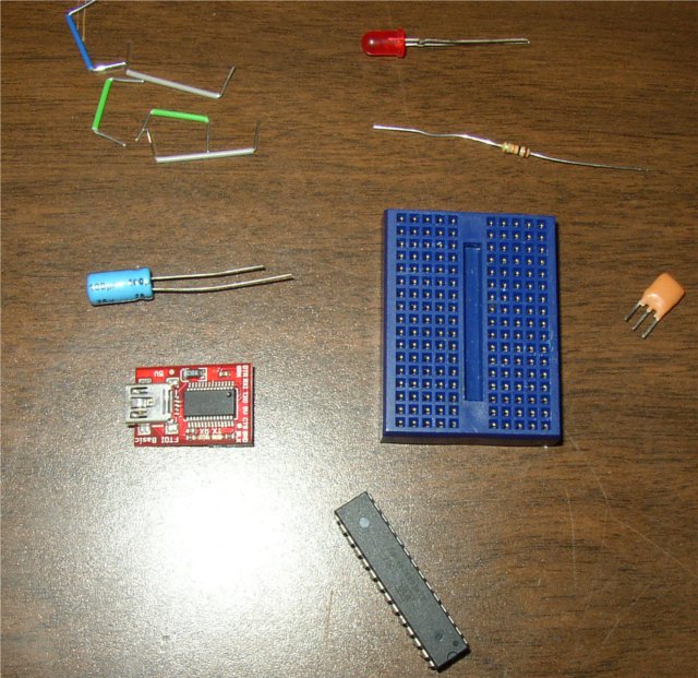
Parts
Step One⌗
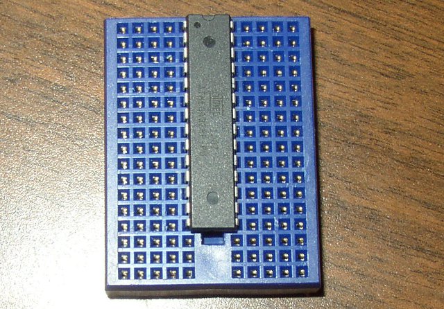
ATMega328P
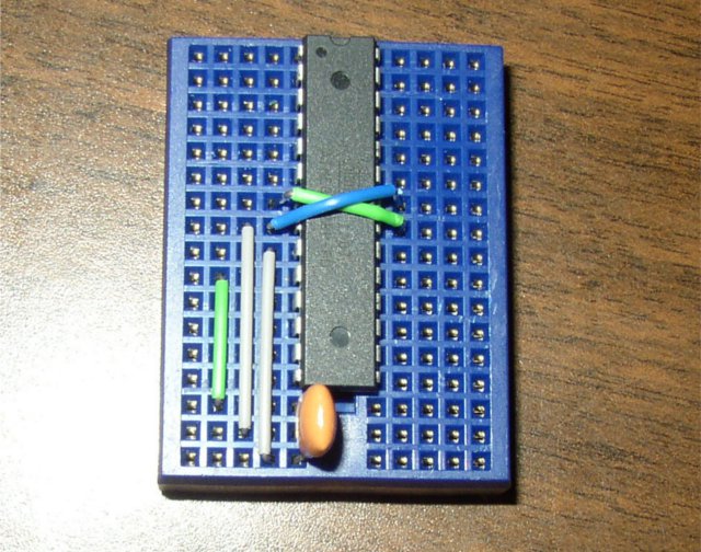
Put the ATMega328 in the breadboard, with the little semicircular cutout facing one end of the breadboard.
Step Two⌗
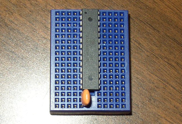
Resonator
Put the resonator in the breadboard in the remaining three pins under the ATMega328, direction doesn’t matter.
Step Three⌗
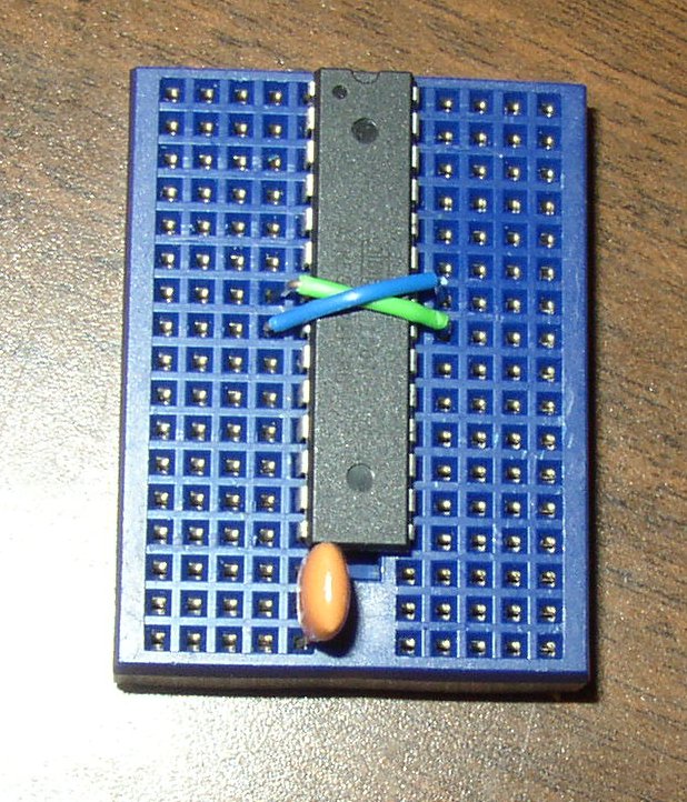
Power
Wire up the power as shown. The green wire is +5v, the blue one is GND. They are supposed to cross, yes.
Step Four⌗
Resonator wiring
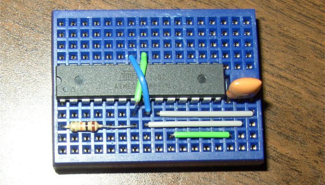
Wire the resonator to the two XTAL pins, the GND pin of the resonator should go the GND. See picture.
Step Five⌗
Pull-up resistor
Put the 10kOhm resistor between +5v and the upper-left pin on the ATMega328 (reset). This will pull it high, and keep it from resetting itself.
Step Six⌗
LED
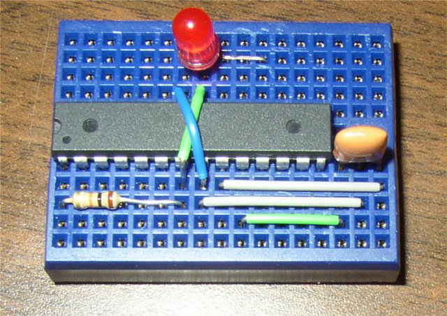
Add the LED between GND and the pin two spaces after GND, see picture. The shorter lead of the LED (-) goes to GND. You will be able to activate this LED by pulling Arduino Pin 13 HIGH.
Step Seven⌗
FTDI
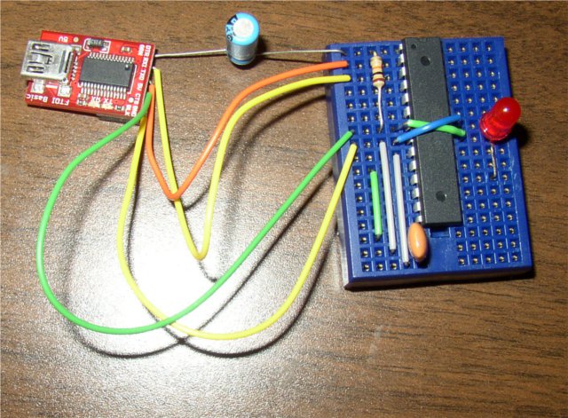
Connect the FTDI serial board. The capacitor is electrolytic, put the negative lead toward the FTDI and the positive lead toward the RESET pin. RxD on the FTDI goes to Tx on the Arduino, and TxD on the FTDI goes to Rx on the arduino (flipped). +5v and GND go where expected.
Read this:⌗
???⌗
Program your board.